Web on/off delay timer circuits are simple electronic circuits that can either turn on or off a circuit after a predetermined time period has passed. Thank you for your time guys. This video walks through how all the elements of an off delay relay work and a practical circuit that it can be used in.👉j.
Relay OFF Time delay timer by using NPN Transistor and Capacitor
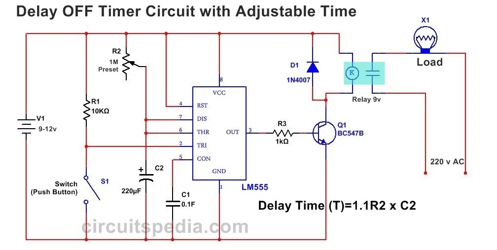
So the time period after which this circuit will automatically turn.
Web Time Delay Relay Circuit Diagram.
Web wiring an off delay control circuit timer with magnetic contactor and h3y relay. Some timers will have instantaneous contacts in. When you press the push of the delay timer then current flows from vcc to gnd.
Web For Instance, It Can Be Used To Stop Electric Motors, Hold Open Doors, Limit Industrial Process Times, Turn On Lights, Or Monitor Temperature Control Systems.
This will help you to create a delay between one event and. Web how the circuit works? Web 5 this may seem simple but i am trying to learn ee.
In The Below Circuit, How Can I Add A Delay When The Button Is Released The Relay Will Stay Energized For Approx.
The use of timers in. Web in ladder diagram, the off delay timer is a part of the off delay switch. Web the below figure is the schematic of a simple automatic on off timer with a fixed timing resistor and capacitor.
Web An Off Delay Timer Relay Wiring Diagram Shows How These Components Are Connected Together.
12v time delay relay] adjustable on off timer(using 555 astable mode) in this circuit a timer with cyclic on off operations is designed. Ac500 plc comm int modules; It provides time before the switch goes off.
Web When It Comes Time To Wire Up A Dayton Off Delay Timer, The Wiring Diagram Is Key.
When the switch is turned off, the relay remains on for a programmed amount of. Web off delay can be a bit confusing. The timer is an electrical device that controls the operation of the equipment by switching on and off.
It’s Important To Note That There Are Two Main Wiring Diagrams For These Types Of.
It's important to have a good understanding of how to wire the. The delay timer circuit is connected with a 12v power supply.