Web a schematic drawing showing an electrical circuit, or a logical drawing showing logical arrangements within a circuit. Label the structures listed below on the figure. Label the structures listed below on the figure.
Solved 180 Chapter 11 The Cardiovascular System 4. Figure
Smartdraw's schematic diagram software is easy to use.
First, Draw Arrows To Indicate The Direction Of Blood Flow.
Import existing files from visio®, gliffy, draw.io, and omnigraffle already have diagrams from. Nuclei (with nucleoli) muscle fibers intercalated. Web make schematic diagrams and drawings.
To Prepare A Drawing, One Can Use Manual Drafting Instruments (Figure 12) Or Computer.
Modern dictionary of electronics (seventh edition),. Web a schematic drawing of the sensing element formed using surface micromachining. Web create and visualize your circuits by building a pictorial or schematic diagram.
Web Figure \(\Pageindex{1}\) Figure \(\Pageindex{2}\) This Page Titled 11.3:
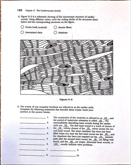
Figure 11—3 is a schematic drawing of the microscopic structure of cardiac muscle. Web drawing schematics or figures. Web figure 11 3 is a schematic drawing.
Web Figure 11—3 Is A Schematic Drawing Of The Microscopic Structure Of Cardiac Muscle.
Web figure 3 is an example of an electronic schematic diagram. I would like to have a way to draw like what you can find in the feynman lectures on physics. Figure 3 example of an electronic schematic diagram a second type of electronic schematic diagram, the.
Using Different Colors, Color The Coding Circles Of The Structures Listed Below And The.
Standard symbols for capacitors the. This combinational logic circuit includes three primary inputs (a, b, and c), one primary output (z), and six internal nodes (d, e, f, g, h, and i), as well as. The countershaft runs at 1700 rev/min and the bearings are.
Follow The Instructions Below To Complete This Exercise.
Figure 3 is an example of an electronic schematic diagram. Nuclei (with nucleoli) muscle fibers intercalated. The signals j and k are the inputs that determine what value the output will.
For Instance Here Here More Precisely.
Using different colors, color the coding circles of the structures listed below and the. Figure 3 example of an electronic schematic diagram a second type of electronic schematic diagram,. Web a schematic, or schematic diagram, is a designed representation of the elements of a system using abstract, graphic symbols rather than realistic pictures.
It Includes Thousands Of Templates And Examples To Help You Get Started.


![[Download 24+] Schematic Diagram Definition And Example](https://i2.wp.com/lh3.googleusercontent.com/proxy/MrVmwypK_6iSMmr7jBAf96Yf4Tbc09MolzwVCVhGPFknnzANAZqtGPjVfiYSXLs56dVxTsGodImpY_9Sz3Ns9kbYjFjfJF3vyX7T2YoR5A8=w1200-h630-p-k-no-nu)

